Home List your patent My account Help Support us
Traction Powered Machine - Alternative Energy
[Category : - RENEWABLE ENERGY]
[Viewed 3609 times]
While summit conferences tackling these Global conditions continue to rage feverishly, everyday, throughout the world, there are millions of tons of free and clean energy that remains untapped – the energy coming from vehicles which use regulated and refined fossil fuel.
Going by the mass and speed with which each vehicle hugs the streets surfaces we could just figure out that there are indeed millions of tons of this energy that could be harnessed to produce hundreds of billions of dollars worth of electricity.
It is for this reason that I am introducing my machine, the traction-powered which can transform forces produced by running vehicles in conjunction with their mass and acceleration.
Ernesto Ganaden
Inventor
[Use the button below to contact me]
09065053448
Field of the Invention
The invention relates generally to the use of an alternative energy
source, and more particularly to a machine that utilizes an energy source
that is free and clean.
Background of Related Art
The use of sustainable source of energy is an art as old as civilization
Itself. Because of the need to produce his basic needs with much less
effort, man has eventually discovered the potentials of wind and water
to turn his simple machines. Thus, the windmill and the water turbine
were born. Later on, solar power and the use of coal to produce steam
came into being.
The discovery, however, of fossil fuel is considered a breakthrough
In the quest for a more sustainable energy source. Not long after, taking
cue from its immense reliability, the internal combustion system was
Invented.
But as automobiles and power generating plants, which are the
direct beneficiaries of the fossil fuel, began to proliferate worldwide, so
did the poisonous gas that the burnt fuel emitted at an alarming rate.
R,A. 9513, also known as the Renewable Energy Act, was enacted
Into law last January 2009, and said to be the most comprehensive
renewable energy law in Southeast Asia.
The problem, however, that arises in the search and development
of these renewable sources of energy is the difficulty to locate and
utilize said sources, and the prohibitive cost it will incur considering
the government’s lack of fund for such exploration.
Purpose of the Invention
The purpose of the invention is primarily to solve the problem
mentioned above by providing for a traction-powered machine.
Another purpose of the present invention is to utilize a free
and clean source of energy that would enable the electric power
generator or other conventional machines to run without the use
of harmful materials.
Another purpose of the present invention is to provide for a
traction-powered machine that is disposed inside a bunker along
a road or the like, and comprising a bar assembly wherein said bar
assembly is provided with a steel bar that protrudes through a steel
frame laid across the surface of said road or the like; together with
said bar assembly is a pair of trapdoors provided on both sides of the
steel bar, and attached at both ends of the base of the steel bar is a
pair of power springs, and also attached at the middle of the base of
said steel bar is a connecting rod that links said steel bar to a gear
assembly which consists of a power pinion and a gear that is mounted
on a shaft which delivers power to the wrapping connector assembly.
Another purpose of the present invention is to provide for a
traction-powered machine whose maximum efficiency is achieved with
a provision for a plurality of said machine wherein as many traction-
powered machines as possible are disposed side by side in rows opposite
each other and in between said rows are one or more wrapping
connector assemblies.
Another purpose of the present invention is to provide for a
traction-powered machine which is equipped with a self-preservation
mechanism wherein said machines in one row have their gears turned
via the ring pawls by the direct force caused by the impact between
tires and the steel bars while said machines in the opposite row have
their gears turned via the ring pawls by the pulling effect of the power
springs retracting to their normal position.
Also another purpose of the present invention is to provide for
a traction-powered machine that is versatile, in which case said machine
can be used to operate conventional machines other than the electric
power generator.
Also another purpose of the present invention is to provide for a
traction-powered machine that is simple in construction and is made of
locally available materials.
Still another purpose of the present invention is to provide for
a traction-powered machine that is easy to operate and requires little
attention.
Other purposes and advantages of the present invention for a
traction-powered machine will become apparent upon reading of the
following detailed description taken in conjunction with the
accompanying drawings.
Brief Description of the Drawings
Figure 1 is a bird’s eye view of a road or the like showing the
present invention’s pair of steel frames and a number of steel bars
within said steel frames.
Figure 1 also shows a cross-sectional view of the powerhouse
wherein the present invention’s partial mechanism is situated;
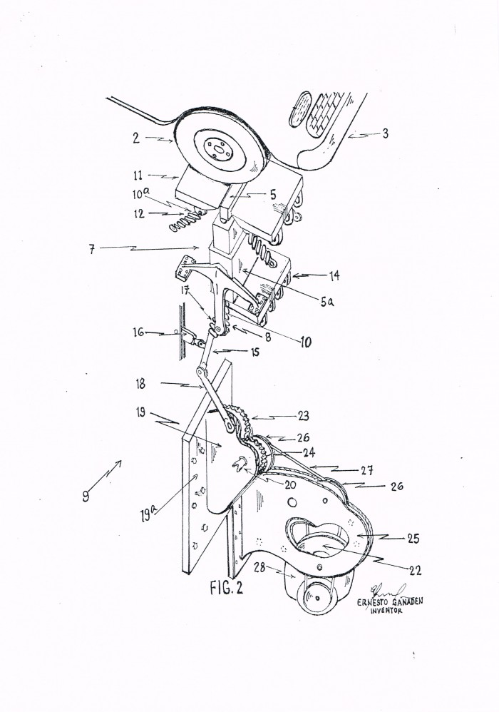
Figure 2 is an elevational perspective view of the present
invention’s single , detached traction-powered machine;
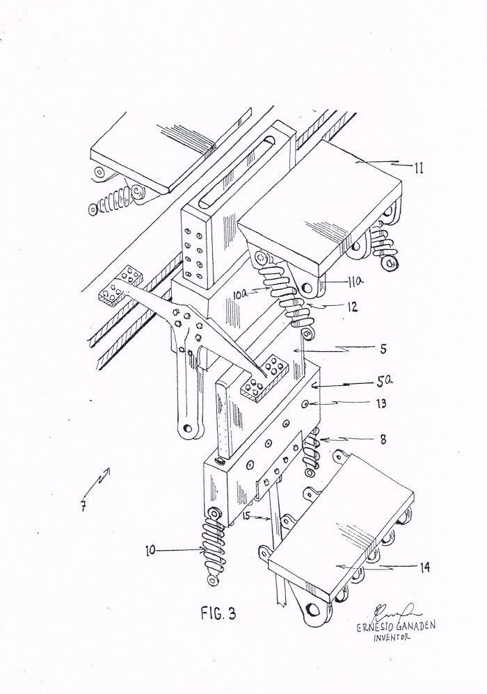
Figure 3 is an exploded view of the bar assembly showing some
of its essential parts and accessories;
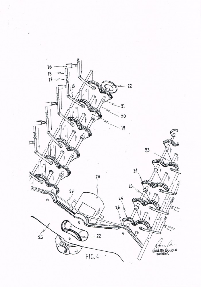
Figure 4 is a perspective view of the present invention’s disposition
of the interconnected traction-powered machines and its provision for
a self-preservation mechanism;
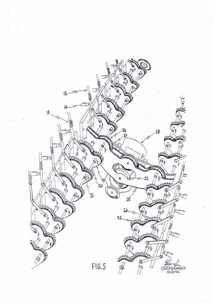
Figure 5 is a perspective view of the present invention’s disposition
of a high-density mechanism; and
Figure 6 is an illustrative view of the gear assembly.
Detailed Description of the Drawings
Referring now to the drawings where some essential parts of the
present invention is designated throughout, there is shown the bird’s
eye view (Figure 1) of a road 1 or the like to depict the purpose of the
present invention which is the use of a free energy source and more
particularly its function which is to utilize the energy coming from
the tires 2 of a running vehicle 3 as illustrated by the steel frames 4
laid horizontally across the said road 1 or the like, and within said steel
frames are enclosed a number of the steel bars 5.
Said present invention for a traction-powered machine which is
generally designated as 9 (Figure 2) will start to work when the tires 2
of a running vehicle 3 run over a plurality of bar assembly 7, each
housing a steel bar. Said bar assembly 7 is bolted on to the beams
just below the surface of the above road 1 or the like. The linear force
created by the impact between the tires 2 and the steel bar 5 is then
absorbed by the pair of opposing power springs 8 wrapped around a
respective vertical shock absorber 10 that are attached to both ends
of the base 5a of the steel bar 5.
To enhance the present invention’s performance, a pair of
opposing trapdoors 11 is pivotally disposed at the sides of said steel
bar 5, each with suspension spring 12 and a plurality of diagonal
shock absorbers 10a fixed beneath thereof and are bolted on to the
steel frame 4 through hinges 11a provided at the bottom edge of said
trapdoors 11. This will allow heavier vehicles to depress said steel bar 5
further down, thus creating more force.
To further enhance the present invention’s performance, the
height of the steel bar 5 which is reciprocating in said base 5a can be
adjusted by loosening the screws 13 (Figure 3) provided thereto for
holding the said bar 5 and tightening them after the desired height is
obtained.
Also provided securely at the bottom of the base 5a of the steel
bar 5 is a stabilizer 14 to prevent said steel bar from tilting sideways
whenever the tires 2 hit said steel bar off-center.
Referring back to said force created as earlier described, said force
would travel along the connecting rod 15 (Figure 4) projecting
downwardly from the bottom of said base 5a. Said connecting rod 15
is held firmly by a pivoted latch 16 next to the cushion spring 17 provided
there to. The lower end of said connecting rod 15 is pivotally connected
to the lever 18 and down the gear assembly 19 that is bolted on to a
steel frame 19a inside a bunker (not shown) disposed inside the
powerhouse 6.
Inside said bunker, a number of the traction-powered machine 9
can be disposed with their shafts 20 interconnected by universal joints
21 all the way to the rear end of each row where a flywheel 22 is
attached and whose function is to gather inertia and to ensure smooth
and continuous rotation of the shafts 20.
Said gear assembly 19 which is disposed below said bar assembly
5, consists of a power pinion 23 where a torque is created by the linear
force brought about by the lever 18, in which case said linear force is
transformed into a rotary force; a mating gear 24 is engaged with said
power pinion 23 and is mounted on the shaft 20.
The rotary force is transmitted to the wrapping connector assembly
25, disposed adjacent to said gear assembly 19. Said wrapping
connector assembly 25 consists of at least one power wheel 26
connected to said mating gear 24, and to at least one flywheel 22 that is
engaged with a power generator or the like via power belts 27.
Figure 4 and 6 show another embodiment of the present invention
which provides a self-preservation mechanism wherein, as indicated by their respective arrows, said machines in one row have their power
pinions 23 turned via the ring pawls 23a by the direct linear force coming
from the impact between the tires 2 and the steel bar 5, while said
machines in the opposite row have their power pinions 23 turned via the
ring pawls 23a by the pulling effect of the power springs 8 retracting to
their normal positions in order that said pulling effect would cancel the
jolts caused by the said impact which is equivalent to a blast in an
internal combustion engine.
Maximum efficiency of the present invention will be achieved in
such a way that provides for a high-density mechanism (fig. 5)
wherein as many traction-powered machines 9 as possible can be
disposed side by side in rows opposite each other with one or more
wrapping connector assemblies 25 provided in between them.
It is to be understood that while certain elements of the present
invention have been illustrated and described, it is not limited thereto
except insofar as such limitations are included in the following claims
and allowable functional equivalents there of.
Claims:
A Traction-Powered Machine adapted to drive a power
generator or the like and disposed along a road or the like, said
traction-powered machine comprising a bar assembly, a gear
assembly disposed below said bar assembly and a wrapping
connector assembly disposed adjacent to said gear assembly; said bar
assembly having a steel bar, a pair of opposing trapdoors pivotally
disposed at the sides of said steel bar, a base provided there of where
said steel bar is reciprocating, and whose height is adjustable through
the screws provided thereto, a connecting rod projecting downwardly
from said base, and a lever pivotally connected to said connecting rod;
said gear assembly having a power pinion connected to said lever, and a
mating gear engaged to said power pinion; said wrapping connector
assembly being defined by at least one power wheel and a belt
connected to said mating gear, and a flywheel being belt-driven by
said power wheel.
2. A traction-powered machine according to claim 1 wherein said
bar assembly further comprising suspension springs with a plurality of
diagonal shock absorbers fixed beneath said trapdoors, a stabilizer
provided securely at the base of said steel bar, and a pivoted latch
holding said connecting rod.
3. A traction-powered machine according to claim 1 wherein
said gear assembly is bolted on to a steel frame provided thereof.
4. A traction-powered machine according to claim 1 wherein
said wrapping connector assembly further comprising at least one
power wheel, connected to said mating gear, and to at least one
flywheel through power belts thereof.
5. A traction-powered machine according to claim 1 wherein
a plurality of bar assemblies are interconnected to respective gear
assemblies driving at least one wrapping connector assembly that is
coupled to at least one power generator or the like.
ABSTRACT
A Traction-Powered Machine adapted to drive a power generator
or the like and disposed along a road or the like, said Traction-Powered
machine comprising a bar assembly, a gear assembly disposed below
said bar assembly, and a wrapping connector assembly disposed
adjacent to said gear assembly; said bar assembly having a steel bar,
a pair of opposing trapdoors pivotally disposed at the sides of said
steel bar, a base provided thereof where said steel bar is reciprocating,
and whose height is adjustable through the screws provided thereof,
a connecting rod projecting downwardly from said base, and a lever
pivotally connected to said connecting rod, said gear assembly having
a power pinion and a mating gear engaged to said power pinion; said
wrapping connector assembly being defined by at least one power
wheel and a belt connected to said mating gear, and a flywheel being
belt driven by said power wheel.
Financial information
I am particularly looking for interested parties for licensing or partnerships.
 Patent publications:
 No published information
Ask the inventor for a copy of the filed application
Asking price:
Make an offer
Make an offer
 Great invention
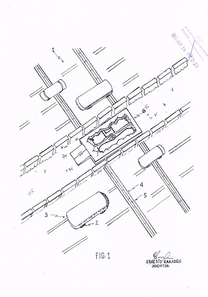
[ Home | List a patent | Manage your account | F.A.Q.|Terms of use | Contact us]
Copyright PatentAuction.com 2004-2017
Page created at 2025-11-26 3:47:27, Patent Auction Time.