Home List your patent My account Help Support us
Soaker Hose with Scalable Premable Surface Area (Echo Hose)
[Category : - CONSTRUCTION HOME IMPROVEMENT]
[Viewed 4219 times]
U.S. Patent Pending application number 61/820,525
2
Ech2o Hose
Contents
Introduction ................................................................................................................................................... 3
Method of estimation of the required contact pressure ................................................................................. 4
Counter balancing the dynamic pressure of the jets by contact pressure developed in the hose-sheath assembly ........................................................................................................................................................ 7
Restrictive force analysis of sheathing “roll back” ..................................................................................... 10
Bibliography ............................................................................................................................................... 11
Appendices .................................................................................................................................................. 12
Appendix A: MATLAB code for generating the plot shown in figures 4 and 7 ..................................... 12
Appendix B: Plots in the case of Waterworks™ porous hose ................................................................ 15
3
Ech2o Hose
Introduction
The Ech2o Hose is principally a modified ordinary soaker hose. A soaker hose is a special hose itself, with micro pores all along its length; unlike an ordinary hose which can only transport water through a flexible rubber tube and eject it through an end opening. Soaker hoses are able to leak all along their length due to their porous wall structure, and the static pressure inside the hose being higher than the outside atmospheric pressure. The Ech2o Hose design incorporates an outer sheath covering the soaker hose which prevents the hose from leaking along its entire length; it also allows the user the flexibility of dictating where and the amount of hose surface area to leak (water) from. This facilitates economy of water usage and what may be termed “selective or targeted watering”. The outer sheath is designed to produce the required compressive force to ensure that water cannot leak through micro pores within the soaker hose walls. An analysis is developed in later sections to demonstrate how the material for the sheath should be selected and how an appropriate thickness can be determined.
Ech2o Hose Construction
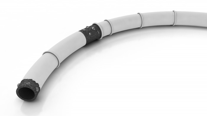
As stated previously, the Ech2o Hose is constructed of a traditional irrigation soaker hose except that it is covered in sections with an elastic rubberized exterior (sheathing). The sheathing has an elastic characteristic which provides sufficient compression upon the soaker hose surface to inhibit its designed permeability, yet it can be rolled back in sectional intervals to expose a selected amount of permeable surface area targeting specific locations of desired irrigation. Each leading edge sheathing length presents with a “grasp ring” (Figure 1) allowing the user to easily grasp a desired “sectional sheathing length” and begin the “roll-back” [see “Restrictive force analysis of sheathing “roll back”, page 10]. Sheathing edges trailing the sheath grasp ring may or may not be adhered to soaker hose through increased sheathing/other material compression, melt welding, and/or adhesive means.
Figure 1: Illustration of the basic concept behind the Ech2o Hose
The Ech2o Hose design can be adapted with varying lengths of sheathing along with varying diameters and lengths of soaker hoses of differing manufactured composition (porosity) combining to meet an endless number of watering application requirements (unlimited number of product lines).
Ech2o Hose Benefits and Uses
The Ech2o Hose provides the traditional benefits of a soaker hose but with a definable area of scalable permeable surface area allowing the user to limit and choose the area to be irrigated unlike the traditional soaker hose and other methods of irrigation. Users of the Ech2o Hose are able to control
4
Ech2o Hose
the permeable surface area of a traditional design soaker hose with one that is scalable, adjustable, and reversible. The Ech2o Hose can be quickly and easily configured/ reconfigured for use/reuse in successive future applications with varying locations of desired irrigation locations without modification or damage to its original construction.
The scalability and reusability of the Ech2o Hose will increase traditional applications of a soaker hose and is a low cost, simple design able to replace numerous other methods of targeted and non-targeted micro irrigation such as drip, misting, and spray in both surface and subsurface irrigation.
The scalability, simplicity, and low cost of the Ech2o Hose can replace other systems and/or increase the incorporation of soaker hose, particularly in uses where the traditional soaker design was limited or not used in targeted irrigation designs. This is due to water permeability upon its entire length resulting in wide area saturation vice targeted, selected area saturation.
The Ech2o Hose design will limit the amount of water released in an irrigation application to only the areas of desired irrigation; eliminating over spray, wide area saturation vice targeted saturation and undesired run-off, and providing an economical means of more efficient irrigation over other methods in the following ways:
Reducing water usage (water conservation)
Reducing power usage in ground water pumping applications (energy conservation)
Reducing non-desired plant and weed propagation
Reduced herbicide usage (environmentally sound)
Reduced mechanical weed tilling, culling (energy conservation)
Increased farming/gardening production yields (increase in productivity, economical)
Increased efficiency in micro and organic farming applications (encourages reduced production/use of herbicides (ecological)
The scalable, easily adjustable, permeable surface area characteristic of the Ech2o Hose eliminates the need for, effort in adaption, and expense of the various fittings, additional hoses, adapters, nozzles, clamps, collars, etc. in other irrigation systems:
Provides means of significantly reducing the expense of any irrigation requirement
Provides ease of design to any irrigation project
Provides immediate adaptability to any existing metered, timed or previously piped system
Method of estimation of the required contact pressure
The fundamental concept behind the Ech2o Hose is demonstrated in Figure 2. A rubber sheath (A) would be stretched over the ordinary soaker hose (B) much like a condom, to halt water seepage from the micro pores within the primary soaker hose. The basic assembly of the sheath(s) and the hose would look as what is shown (C) in Figure 2. The sheath’s inner diameter is
5
Ech2o Hose
initially going to be slightly less than the outer diameter of the soaker hose itself.
Figure 2: Detailed illustration of the hose-sheath assembly
This would allow the sheath and the hose assembly to develop the required contact stress once the sheath(s) are installed over the hose. It is integral to understand that the leaking which occurs without the sheathing takes place because there is a difference in the static pressures outside (Patm) and inside (P) the soaker hose. When the pressure outside the soaker hose is made equal or greater than that to the inside the tube (Patm=P), there would be no water “bleeding or leakage”. Within a closed system (hose with closed end), the pressure inside the soaker hose will be higher than the atmospheric pressure. In fact the former (4.5 atm max.) can be as high as more than four times the latter (1 atm). When sheathing the soaker hose with an appropriate material a radial compressive force can be created to produce an increase by 3.5 atm in the outside pressure, as has been indicated earlier, the leaking would stop.
In practice, the extra pressure that has to be applied does not have to be as high as 3.5 atm. It is principally because there would be a significant loss of energy of the water as it passes through the micro pores of the soaker hose. So pressure reinforcement (Pextra) much lower than 3.5 atm will suffice in almost all cases; however, the exact requirement of pressure reinforcement will be dependent upon the material composition, number of pores per unit area (pore density) and variability of pore sizes of the soaker hose that has to be sheathed. The irregularity of the pore sizes and even shapes have to be considered as they are not simple perforations. For concept demonstration and the purpose of development of an accurate and simple theoretical analysis, it may be assumed that there is no pressure loss of the fluid as it passes through the soaker hose wall structure. Assuming there is no pressure loss in the pores is equivalent to assuming Pextra ≤ 3.5 atm which must be provided by the contact pressure developed by the sheath-hose assembly. Progressing with this assumption characterizes the conservative analysis of this approach since the known pressure loss of the water passing through the soaker hose micro pores is ignored, which would result in prediction of a much higher required sheath thickness than what would actually be required.
The water jets coming out of different pores have a large variation in bleeding velocity. If the highest velocity found is v, the maximum velocity pressure (dynamic pressure) is:
6
Ech2o Hose
As Pjet is the highest pressure the sheath would experience on its inner surface. It can also be understood that Pjet ≤ 3.5 atm. It has to be stressed here that the actual value of Pjet can be expected to be much less than the maximum of 3.5 atm, considering the loss encountered in pores which are very small labyrinth of openings. Moreover, the less the static pressure inside the tube, the less will be Pjet and consequently the less will be the magnitude of required contact pressure. Another factor that will further reduce the pressure exerted on the external sheath is the fact that the pressure inside the hose would have a dynamic component associated with it. The forward momentum of the fluid particles will make it harder for them to escape through the pores. Additionally the irregular and rough interior surface of the soaker hose would further reduce the water momentum.
A flow regulator may also be incorporated within the hose coupling to the water source (common within existing soaker hose products), for controlling the flow rate permitted into the Ech2o Hose. A dynamic flow regulator (simple small aperture insert within the hose coupling) can create even a further energy loss of the supply water which will result in an even lower value of the maximum jet speed v in equation 1. This consequently would mean a lower radial pressure would be exerted on the sheath’s inner surface; further demonstrating the practically of the sheathing concept within the following contact pressure required analysis.
Using well established mechanical principles, it is possible to get an estimate of the initial soaker hose “water jet” velocity. In analysis of a selected water jet while the hose is in operation, and oriented as to the jet shooting vertically upward and measuring the height of the fountain the jet creates, (h) can be established. Thusly the initial velocity can be computed by:
A pore might produce a jet not perfectly vertical but inclined at a certain angle with the hose lying horizontal. In such cases it is required to estimate the height of the jet, which can be found simply by applying the Pythagorean principle after the length of the fountain and its angle of inclination have been recorded. It should also be mentioned here that the method of estimating the jet velocity in this manner does not take in to account the air resistance and therefore would not produce an accurate value (ignoring the factor of air resistance here incorporates additional conservatism into analysis). However, it still will be give a fairly useful estimate about the strength of the jet and the velocity pressure it would exert.
Plugging in this expression into equation 1:
7
Ech2o Hose
Counter balancing the dynamic pressure of the jets by contact pressure developed in the hose-sheath assembly
Figure 3: The hose-sheath assembly and relevant dimensions
The contact pressure developed by any assembly is given by (Budynas & Nisbett, 2011)
Here,
p is the developed contact pressure,
δ is the deflection in the radius of the sheath or the radial deflection,
Eo is the modulus of elasticity of the material of the hose,
Ei is the modulus of elasticity of the material of the sheath,
νo is the Poisson’s ratio of the material of the hose,
vi was the Poisson’s ratio of the material of the sheath,
ro is outer radius of the sheath after assembly,
ri is the inner radius of the hose after assembly and
R is the inner radius of the sheath after assembly.
Equation 3 essentially describes a linear relationship between the radial interference (δ) and the developed pressure (p) because for a particular assembly the denominator is a constant as it contains material property constants and fixed dimensions.
A typical δ-p plot for a hose-sheath assembly is in Figure 4. Each straight line represents a particular option for the material of the sheath, while the hose material stays the same. The straight lines pass through the origin, indicating that if the radial interference (δ) is zero, no contact pressure (p) would develop in the assembly.
Figure 4: A typical radial interference versus developed contact pressure plot.
Equation 3 can be used to predict the required modulus of elasticity and Poisson’s ratio of the material of the sheath. Since the sheath must possess the ability of being rolled and unrolled over the hose, it is essential to keep in mind that the thicker sheathing requirement (the thickness is represented by ro-R according to the notations presented in Figure 3) the less 01020304050600123456Pressure (PSI)Delta (mm)Compressive force per unit area versus deflection required in the radius of the sheath Eo=0.025 GPaEo=0.050 GPaEo=0.075 GPaEo=0.01 GPa
8
Ech2o Hose
practical the design concept becomes. If the choice of a particular rubber is made as the sheath material, using its respective values of modulus of elasticity and Poisson’s ratio it is easy to predict the dimensional requirements i.e. the sheath thickness (ro-R) and the radial interference (δ).
The δ-p equation can also help in studying the feasibility of different materials and individual thickness requirements of the sheath. Since the required sheath thickness is given by the difference between ro and R, if the latter is considered fixed, appropriate values of ro can be extracted from Equation 3 considering all other parameters constant for different radial interferences. However, Equation 3 has to be processed for this to be accomplished. The form that is sought is as follows.
From Equation 3,
The above equation can be used:
This yields a very useful form of Equation 4:
In equation 5, of course,
It is notable here; that Equation 4 is necessarily of the same form presented in Equation 3, and as four variables cannot be accommodated in a single two dimensional graph to obtain a particular value of elastic modulus of the sheath material, values of ro can be calculated for different contact pressures (p) and radial interferences ( ) instead. Once ro is obtained, sheath thickness can be computed subtracting R from it. A typical plot is shown below (the MATLAB code has been provided in appendix). It has to be noted that beyond a critical pressure the curves produced using Equation 5 exhibit abrupt discontinuities, indicating that after that critical point, no practical solutions for thicknesses are possible.
Figure 5: Sheath thickness vs. contact pressure for different interferences for rubber with Eo of 0.025 GPa
A conspicuous property of the individual curves produced in Figure 5 using Equation 2 is that they eventually become asymptotes to the axis representing the sheath thickness. This happens dramatically once the pressure reaches a certain critical value. For =0.0025 mm, for example, the value of the critical pressure is about 35 PSI. This
010203040506000.20.40.60.811.21.41.61.8Pressure (PSI)Sheath thickness (mm)Sheath thickness vs. pressure for different interferences for rubber with E of 0.025 GPa delta=0.0025 mmdelta=0.0050 mmdelta=0.0075 mmdelta=0.01 mm
9
Ech2o Hose
essentially means that if for =0.0025 mm and Eo=0.025 GPa we want to produce a pressure beyond 35 PSI, no matter how much we increase the sheath thickness, it would not be effective as is shown by the steep rise of the curve.
The critical pressure (Pcr) can be determined by the equation:
However, this condition would be difficult to apply in trying to find a useful expression for Pcr. Additionally it can be seen that the following condition is also valid.
From Equation 5,
Therefore,
Since R is a constant in any particular case, simplifying the above expression follows:
Inserting the expression for X in the above equation, it becomes:
This equation can be processed to a form which is simpler by identifying the constants with large expressions and using single letter constants to represent them and simpilifing:
Here all the Ks are constants. For certain assembly, for example:
Expressions for K3 and K4 can be found similarly.
We can naturally write
Here, C is a constant.
Solving Equation 6 would give us the value of the critical pressure for a certain assembly and a certain permissible value of radial
10
Ech2o Hose
interference. Determination of the constant C would be possible from our knowledge that the curves pass through the origin since for zero radial interference there would develop no contact pressure.
Figures 4 and 7 can help a designer reach a conclusive decision about the required thickness and original inside radius of the sheath.
Restrictive force analysis of sheathing “roll back”
Figure 6: A simple roll
Figures 6 and 7 illustrate the basic geometric properties of a simple roll and a “dual roll” respectively, the second occurring when a sheath is rolled around a shaft with a circular cross section.
Figure 7: A “dual roll” of a sheath around a shaft of circular cross section
In this document, a single coil is also referred to as a “simple roll”. Understanding how a simple role persists in its coiled state is a key to explaining how the “dual role” can stay stable.
In the case of a simple roll, and that of a “dual” roll as well, as will be seen later, curving of the plane surface results in tension in the outer fibers and compression in the inner fibers. The combination of tension and compression in these fibers results in the development of a restoring moment which wants to force the coil to its planar state. This is well exemplified when one tries to roll a sheet of paper. The paper always tries to return to its original state. The paper would always return to its previous state until it becomes fatigued from continuous efforts of being curved. It will, however, not go back to being a planar object if the frictional force that develops in between the contact surface is strong enough to resist the restoring moment developed due to the curvature.
Figure 8: Sheath curvature and developed moment
11
Ech2o Hose
Figure 9: Cross section of the sheath
ro is the radius of outer fiber,
ri is the radius of inner fiber,
h is the depth of section,
co is the distance from neutral axis to outer fiber,
ci is the distance from neutral axis to inner fiber,
rn is the radius of neutral axis,
rc is the radius of centroidal axis,
e is the distance from centroidal axis to neutral axis and
M is the bending moment; positive M decreases curvature.
The moment created is a function of the strain encountered. For the outer surface, the maximum algebraic stresses are (Budynas & Nisbett, 2011)
These equations can be used to calculate the maximum moment that develops in the sheath. The cancelling moment in a stable roll is developed due to the friction force created in between the surfaces in contact. This force is dependent on the friction factor of the surfaces themselves and the amount of surface in contact. The larger the surface area in contact the more difficult it would be for the sheath to go back to its original state.
Bibliography
Budynas, R. G., & Nisbett, K. J. (2011). Shigley's Mechanical Engineering Design (Ninth ed.). New York: McGraw Hill.
12
Ech2o Hose
Appendices
Appendix A: MATLAB code for generating the plot shown in figures 4 and 7
%%%%%%%%%%%%%%%%%%%%%%%References%%%%%%%%%%%%%%%%%%%%%%
%Hose material properties (elastic modulus and poisson’s ratio) were taken from Link
%The possible sheath material properties have been obtained from Link
%%%%%%%%%%%%%%%%%%%%%%%%%%%%%%%%%%%%%%%%%%%%%%%%%%%%%%%
Ehose=3.44*(10^6); %Elastic modulus of the hose material
Poissonhose=0.5; %Poisson's ratio of the hose material
Esheath=(0.025*(10^9):0.025*(10^9):0.1*(10^9))'; %Array for different elastic moduli of the sheath material
Poissonsheath=0.5; %Poisson's ratio for the sheath material
P=(0.01*10^6:0.01*10^6:0.45*10^6)'; %Possible deflections
ro=0.00762; %Outside dia of the total assembly in meters; A rough value has been used
ri=0.00508; %assuming a rough wall thickness
R=0.00635; %Nominal diameter of the hose
%code for plotting the del-p curve
for n=1:numel(Esheath)
fprintf('nFor rubber of Elastic modulus %d GPAn', Esheath(n)/10^9);
fprintf('n%6s %12sn','P (PSI)','del (mm)');
for m=1:numel(P)
Ex1=((ro^2+R^2)/(ro^2-R^2))+Poissonsheath;
Ex2=((ri^2+R^2)/(-ri^2+R^2))+Poissonhose;
Expression(n)=((1/Esheath(n))*(Ex1))+((1/Ehose)*(Ex2));
del(m)=P(m)*(R*Expression(n));
A=[P(m)/6894.744825 del(m)*1000];
fprintf('%6.2f %12.8fn',A);
end
if n==1
plot(P/6894.744825,del*1000,'k');
elseif n==2
plot(P/6894.744825,del*1000,'b');
elseif n==3
plot(P/6894.744825,del*1000,'g');
else
plot(P/6894.744825,del*1000,'r');
end
xlabel('Pressure (PSI)');
ylabel('Delta (mm)');
title('Compressive force per unit area versus deflection required in the radius of the sheath');
legend('Eo=0.025 GPa','Eo=0.050 GPa','Eo=0.075 GPa','Eo=0.01 GPa');
hold on;
end
xlim([0 65]);
ylim([0 6]);
%Code for generating plots with fixed delta and material properties. One
%plot for each material (i.e. one modulus of elasticity)
hold off; %starting new plots
13
Ech2o Hose
delta=(0.0025:0.0025:0.01)';
fileID = fopen('exp.txt','w');
for n=1:numel(Esheath)
figure;
for m=1:numel(delta)
for s=1:numel(P)
funca(s)=(delta(m)/(P(s)*R))-(1/Ehose)*Ex2;
X(s)=(Esheath(n)*funca(s))-Poissonsheath;
thickness(s)=(R*(((X(s)+1)/(X(s)-1))^0.5))-R;
%Section for dealing with undesired data
if (thickness(s))0
thickness(s)=NaN;
fprintf(fileID,'ncomplex');
end
%section for dealing with undesired data ends here
fprintf(fileID,'nfor P=%d thickness is %d',P(s),thickness(s)); %writing data to a file
end
%this section sets different colors for different delta curves
if delta(m)==0
plot(P/6894.744825,thickness*1000,'k');
end
if delta(m)==0.0025
plot(P/6894.744825,thickness*1000,'b');
end
if delta(m)==0.0050
plot(P/6894.744825,thickness*1000,'g');
end
if delta(m)==0.0075
plot(P/6894.744825,thickness*1000,'r');
end
if delta(m)==0.01
plot(P/6894.744825,thickness*1000,'m');
end
%section for labels and limits of axes
xlabel('Pressure (PSI)');
ylabel('Sheath thickness (mm)');
xlim([0 65]);
ylim([0 1.8]);
hold on;
end
%section for setting plot titles for different elastic moduli
if Esheath(n)==0.025*(10^9)
title('Sheath thickness vs. pressure for different interferences for rubber with E of 0.025 GPa');
elseif Esheath(n)==0.050*(10^9)
title('Sheath thickness vs. pressure for different interferences for rubber with E of 0.050 GPa');
elseif Esheath(n)==0.075*(10^9)
14
Ech2o Hose
title('Sheath thickness vs. pressure for different interferences for rubber with E of 0.075 GPa');
else
title('Sheath thickness vs. pressure for different interferences for rubber with E of 0.01 GPa');
end
legend('delta=0.0025 mm','delta=0.0050 mm','delta=0.0075 mm','delta=0.01 mm'); %setting legend for different deltas
end
end
15
Ech2o Hose
Appendix B: Plots in the case of Waterworks™ porous hose
The elastic modulus for the material of the Waterworks™ hose has a value of about 29 MPa. Using Ehose = 29 MPa, the -p and (ro-R)-p plots can be reproduced.
It is notable that for a larger value of Ehose, the critical pressure is encountered well beyond the range that is usually present in domestic water supply systems as can be seen in the above figures. This finding is significant in that it soundly substantiates the practicality of the Ech2o Hose design concept.
Financial information
Evaluated market area: Immense and worldwide
 Patent publications:
 No published information
Ask the inventor for a copy of the filed application
Asking price:
Make an offer
Make an offer
 Great invention
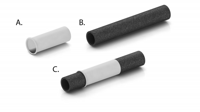

[ Home | List a patent | Manage your account | F.A.Q.|Terms of use | Contact us]
Copyright PatentAuction.com 2004-2017
Page created at 2025-11-26 3:25:08, Patent Auction Time.