Home List your patent My account Help Support us
Adjustable Resistive Prehension Hand Rehabilitation Device
[Category : - MECHANICAL ENGINEERING- HUMAN NECESSITIES- HEALTH]
[Viewed 2819 times]
This invention is a reconditioning , rehabilitating exercise device primarily designed for use in the field of Physical Medicine and the Rehabilitation Department of Occupational Therapy.This device creates and produces a prehensile, reconditioning, and strengthening exercising motion emphasizing the cylindrical, spiraling, helical curving, and oblique angling movements of the metacarpal areas of the hand. This reconditioning and strenthening motion would also involve other areas of the fingers, wrist, and forearm involving radial and ulnar deviation. Up to now, there hasn’t been a reconditioning device that directly targets the twisting force caused by the prehensile action of the cylindrical and helical curving movements involving the entire metacarpal regions of the hand. These particular movements are usually made during a “working action” type of situation where the movements are not premeditative or accomplished of in calculated steps. They are everyday movements that are unconsciously made, such as removing tops from jars and bottles, or turning any type of circular knob, such as a doorknob or control knob, especially those with much resistance. After injuring metacarpal regions of the hand, these simple, non-premeditative movements can be extremely painful and can prevent a person from making them.
1
Because of the uneven twisting force being applied to the muscles and tendons surrounding the many small bones of the hand, these exact movements are often difficult to duplicate during occupational therapy sessions using the current exercising equipment available today for the fingers, hand, wrist, or forearm. The device focuses on these diagonal, uneven, oblique angling movements of the hand that are unconsciously and uncalculatingly made during any type of physical action. There is an exercise device, already available on the market, that has relation to mine involving the reconditioning aspects of the hand. It is the “Rolyan Resistive Prehension Bench”. “Rolyan” is a trademark owned by Smith and Nephew Companies. Compared to my device, there are limits to its usage, such as its accessibility, or position adjustability, and also limits to its direct targeting of the injured or weakened area of the limb. Also, it uses less efficient means for resistance and prehension. My device includes a machined mechanism with small gears, while the “Rolyan’s” device is made up of springs, connected to a board, which can easily wear. Thus, my device is much more durable and provides much more efficient movement, or action. The main similarities between the two exercise devices are some of the resulting movements of the hand, fingers, wrist, and forearm when operating the device. There are also some similar styles of knobs used for turning or holding.
BRIEF SUMMARY OF THE INVENTION
This invention is a rotating, rehabilitation exercise device for the hand,
fingers, wrist, and forearm with adjustable ranges for resistance and prehension. The device includes different, switchable gear ranges and two separate chucks, one on each end of its body. The chucks are adaptable to hold many different sizes, shapes, textures, and styles of turning knobs. The different gear ranges of this device are used for different ranges of resistance needed for reconditioning exercises, and the variety of different styles of turning knobs are used for different ranges of prehension, or grasping and seizing actions made by the hand, which are also used for rehabilitation. In order to use the device, a person would take hold of, or grasp, one of the turning knobs, connected into one of the chucks, with one of his/her hands and then would try
2
to turn the knob. The person would have the option of choosing and using different settings of turning tension, or resistance, by means of a switch. The person would also have the option of choosing and using different grades of prehension by switching to different styles and sizes of turning knobs. These turning knobs have unlimited travel in either direction without change in resistance.The device is fully adjustable to different heights, angles, positions of rotation, and positions of overall support by means of an adjustable, sturdy, telescoping, tripod stand, with a universal, ball-bearing- type clamp that connects to its body and can be manuevered into practically any position or angle. The “Rolyan Resistive Prehension Bench”, mentioned in “BACKGROUND OF THE INVENTION”, incorporates similar types of knobs that can be grasped and turned by the hand but are affixed to springs that are attached to a flat square surface, or plate. When one of these “Rolyan” knobs is turned, the spring, that is attached to the knob, also turns. This enables the spring to expand out and compress in, causing its tension to constantly change at any point, in any direction. Since the tension, or resistance, constantly changes everytime the knob is moved, treating and strengthening the targeted injured area becomes less efficient and much more time consuming, extending the healing period. Also, another negative aspect of these “Rolyan” turning knob springs is that they tend to wear as a result of the periods of constant turning and stretching.
An unchanging, consistent degree of resistance that is concentrated directly on the injured, or weakened area, is what is needed for maximum efficiency. This is what my invention offers. There are also other currently used treatment devices, already on the market, that involve simply the use of ordinary nuts and bolts that can be connected to a board or platform. These nuts and bolts are to be turned by the hand, thus creating a reconditioning exercise. Again, this is a less efficient way in directly treating the injured area, especially the metacarpal areas of the hand, since there is no specific adjustment for tension, or resistance, involved with the free-flowing movement of nuts riding along the threads of bolts. Also, there are limited amounts of travel of the nuts and bolts when coming to the beginning or end of their stop, whereas the turning knobs in my device offer unlimited travel in either direction without change in resistance. Since my device is supported by an adjustable stand, it can be positioned next to any raised platform, such as an edge of a table
3
top, sofa or arm chair rest. By doing this, a person, in turn, is able to actually brace his/her forearm or wrist, the one designated for the rotating exercise, with the remaining hand, thereby isolating a desired part of the limb from any movement involved with the exercise device. By doing this, a person would be able to directly target a specific area for full concentration of treatment from the exercise. With the “Rolyan Resistive Prehension Bench”, mentioned earlier, this procedure can not practically be accomplished. The turning knobs and springs are all affixed to a square, metal plate which is supported by four stationary legs that measure approximately five & one half inches. A person has to stretch his/her arm over a top flat bench filled with protruding turning knobs, reaching over other knobs in order to get to one particular knob of his or her choice. Because of this lack of flexibility, a person is not able to effectively isolate a required or desired part of the hand or forearm for a required movement of a rehabilitative exercise. My invention eliminates these problems and is designed for maximum efficiency.
Anyone who has ever fractured one or more of the metacarpals of their hands has definitely
experienced one of the worst pains imagineable when simply trying to perform a simple task of turning a top off from a bottle or jar. It is a “hard to rehabilitate” type of spiraling, twisting motion involving the entire hand. It involves parts of the hand not usually thought of as even
being related to that type of movement. Besides the metacarpal regions, the exercises created by
my device also involve the strenthening and reconditioning of many other related areas of the hand, fingers, wrist, and forearm.
BRIEF DESCRIPTION OF THE SEVERAL VIEWS OF THE DRAWING
FIG. 1 represents the entire invention, in which the exercise device is connected to its support stand by means of its adjustable mounting bracket.
FIG. 2 is an up-close, side view of the exercise device, without its support stand.
4
FIG. 3 is the same view of that in FIG. 2 except that it displays reference characters used for descriptive purposes.
FIG. 4 is a front view of the exercise device, without its support stand.
FIG. 5 is a rear view of the exercise device, without its support stand.
FIG. 6 is a side view of the exercise device, without its support stand.
FIG. 7 is simply a front view of the exercise device connected to its adjustable ball - clamp assembly by means of its mounting bracket.
FIG.’S 8 thru 14 display different styles of turning knobs that can be used when connected to the exercise device.
FIG.15 displays a locking key that can be used to lock or unlock chucks on the exercise device when changing to different styles of turning knobs.
FIG. 16 is an exploded view of the geared - mechanism portion of the exercise device which in turn delivers the different grades of constant resistance in either direction.
FIG. 17 is a view of a person actually using the claimed invention in a rehabilitative manner while isolating the working limb.
DETAILED DESCRIPTION OF THE INVENTION
The invention refers to a rotating, rehabilitation exercise device for the hand, fingers, wrist,
5
and forearm .The device includes different, switchable gear ranges and two separate chucks, one on each end of its body. The chucks are adaptable to hold many different sizes, shapes, textures, and styles of turning knobs. The different gear ranges of this device are used for different ranges of resistance needed for reconditioning exercises, and the variety of different styles of turning knobs are used for different ranges of prehension, or grasping and seizing actions made by the hand, which are also used for rehabilitation.The device contains small gears which are enclosed and secured within an overall, protecting shell, or casing.
As demonstated in FIG. 17, a person is sitting at the edge of a table top 17 while using the reconditioning device. The person is shown isolating the wrist of the injured hand with the other free hand while turning a knob 6, which is part of the reconditioning device 5. This device is
connected to a fully, adjustable ball – clamp assembly 1, which is adjusted by use of a large, sturdy wing bolt. This ball –clamp assembly, in turn, connects to a mounting bracket 2 which is connected within the center body of the device. The mounting bracket contains a hexagonal-shaped female opening, FIG.6, 2D., which runs from the inside center region of the device and protrudes thru both sides of its body, FIG.7, 2D., allowing the device to be mounted to its
support stand from either side and fit tightly around the male hexagonal-shaped shaft of the ball-clamp assembly, FIG.7, 1A., when connected. It is tightened down with the wing bolt, FIG.6 and 7, 2A., which is connected thru the female opening of the mounting bracket. In FIG.17, ball - clamp 1 fits snuggly into a tripod - shaped, teloscoping support stand 4. Both the ball - clamp 1 and the rest of the support stand are height adjustable by means of the adjusting wing bolts 3. The entire support stand, the ball - clamp, and the mounting bracket allow for the exercise device to be fully adjustable to different heights, angles, positions of rotation, and positions of overall support and are all most likely to be made of metal. There are also manual switches, displayed in 9 and 9A, FIG. 17, that are mounted onto the device, which are used for switching to different levels or grades of resistance or tension that are felt as a result of rotating the turning knob of the device. The person can turn the knob in either direction, at any time, and at any specific point of its travel with absolutely no change in its predetermined resistance setting. The resistance always remains constant at any point of the turning knob’s rotation.
6
In FIG. 3, a larger view, the turning knobs 6 can be made of either plastic or metal, depending upon the different styles used, and their connecting rods, or shafts 6A are most likely made of metal. These shafts are connected into chucks 7 and 7A. These chucks can be made of either metal or plastic and lock the rods of the turning knobs into place. Three types of chucks can be used; two being keyless and one standard. Chuck 7 is the standard type that must utilize a locking key, while chuck 7A is keyless and may be locked or unlocked simply by use of the hand. Chuck 7A can be one of the two basic types of keyless chucks, either being of the push-pull, quick-disconnect style, or of a turn and locking style. FIG. 15 displays a key with a male toothed end that can be used for locking and unlocking the standard types of chucks.
The chucks are internally connected to small geared mechanisms, with each chuck having its own set on each end of the exercise device. FIG. 16 displays the internal composition of just one chucked end of the exercise device connecting to its one individual set of geared mechanisms. The turning knob, turned by hand, turns the chuck 7 which turns a disc 10 which turns three small gears 11 which turns another disc 13. Disc 13 is similar to disk 10 except that its entire perimeter, 13A, is toothed, or geared. Disc 13 also has a gear permanently affixed to its backside. Disc 13
turns another set of three small gears 14 which all ride along the inside of a toothed ring 15 which is stationary and does not move with any of the other moving gears. Next, these three small gears move a final gear 16 which connects to a shaft. When using this device, a person’s hand manually turns these same geared mechanisms by means of the turning knob. This series of gears, when working in combination with each other, is what produces the frictional turning resistance needed from the device. The switch 9, used for adjusting resistance, is connected to a large ring with geared teeth on its inside perimeter. When this switch is positioned back, away from the chuck area, the large ring 12 drops or wedges down into a recessed seat towards the chuck area, between 7 and 10, and locks into a stationary position allowing only the three small moveable gears 11 to move. While the switch is in this position, only these three small gears ride along the inside of this now stationary large ring 12 while the chuck is being turned. When the switch is positioned forward towards the chuck area, this same large ring raises up, out of its recessed seat, and this time, not only surrounds the three small gears as before, but now also surrounds the
7
larger geared perimeter section 13A of disc 13. Since the large ring is no longer locked in its recessed position as before, it is now in a floating position while it surrounds both sets of gears 11 and 13 and moves along with them as one. Because of this newly added help provided by the large ring 12, the chuck, and therefore the turning knob, becomes much easier to turn. This is how my device can provide adjustable grades, or levels of turning knob resistance, all with the touch of a switch. On this device, there are two chucked ends, each having their own set of gear adjustments. One chucked end of the device would produce a series of different levels of lower turning resistance, or easier turning tension. Internally, it would consist of smaller geared mechanisms with smaller, finer teeth, while the opposite end of the device would produce a series of different levels of higher turning resistance, or harder turning tension, internally consisting of larger geared mechanisms with larger, coarser teeth.ABSTRACT OF THE DISCLOSURE
A rotating, rehabilitation exercise device used for the hand, fingers, wrist, and forearm. The device includes different, switchable gear ranges and two separate chucks, one on each end of its body. The chucks are adaptable to hold many different sizes, shapes, textures, and styles of turning knobs. The different gear ranges of this device are used for different ranges of resistance needed for reconditioning exercises, and the variety of different styles of turning knobs are used for different ranges of prehension, or grasping and seizing actions made by the hand ,which are also used for rehabilitation. In order to use the device, a person would take hold of, or grasp, one of the turning knobs, connected into one of the chucks, with one of his/her hands and then would try to turn the knob. The person would have the option of choosing and using different settings of turning tension, or resistance, by means of a switch. The person would also have the option of choosing and using different grades of prehension by switching to different styles and sizes of turning knobs. These turning knobs have unlimited travel in either direction without change in resistance.The device is fully adjustable to different heights and angles. It is supported by a strong, telescoping, tripod-type stand, with a universal, ball-bearing- type clamp that connects to its body and can be manuevered into practically any position or angle. Since my device is supported by an adjustable stand, it can be positioned next to any raised platform, such as an edge of a table top, sofa or arm chair rest. By doing this, a person, in turn, is able to actually brace his/her forearm or wrist, the one designated for the rotating exercise, with the remaining hand, thereby isolating a desired part of the limb from any movement involved with the exercise device. By doing this, a person would be able to directly target a specific area for full concentration of treatment from the exercise.
10 LEGENDS :
FIG.1 : [ Full view of invention ] :
1. Ball-clamp assembly
2. Mounting bracket
2A. Mounting bracket wing bolt
3. Wing bolts ( height and rotational adjustment points )
4. Tripod stand
5. Exercise device
FIG.2 : [ Side view of exercise device without its support stand ]:
FIG.3 : [ Side view of exercise device without its support stand ]:
2. Mounting bracket
2A. Mounting bracket wing bolt
5A. Body of exercise device
6. Turning knobs
6A. Connecting rods of turning knobs
7. Chuck [ standard – for use with key ]
7A. Chuck [ keyless]
8. Labeling for levels, or grades, of resistance [ upper end of device ]
8A. Labeling for levels, or grades, of resistance [ lower end of device ] 9. Resistance selector switch [ upper end of device ]
9A. Resistance selector switch [ lower end of device ]
11
FIG.4 : [ Front view of exercise device ] :
2A. Mounting bracket wing bolt [ top view ]
2B. Mounting bracket [ left-side face ]
2C. Mounting bracket [ right-side face ]
6C. Turning knob [ larger sized ]
6D. Turning knob [ smaller sized ]
FIG.5 : [ Rear view of exercise device ] :
2B. Mounting bracket [ left-side face ]
2C. Mounting bracket [ right-side face ]
6C. Turning knob [ larger sized ]
6D. Turning knob [ smaller sized ]
9B. Resistance selector switch [ top view ]
FIG.6 : [ Side view of exercise device ] :
2A. Wing bolt [ mounting bracket adjustment ]
2D. Hexagonal opening and the face of mounting plate of the mounting bracket
5B. Center region of outside shell of exercise device
3. Center region of outside shell of exercise device
FIG.7 : [ Front view of exercise device connected to ball-clamp assembly ] :
1A. Hexagonal rod - shaped male shaft portion of ball-clamp assembly
2A. Wing bolt [ mounting bracket adjustment ]
2D. Hexagonal opening and the face of mounting plate of the mounting bracket
5B. Center region of outside shell of exercise device
12
FIG. 8 - 14 : [ Different styles of turning knobs ]
FIG. 15. : [ Locking key, for use with standard chucks ]
FIG. 16 : [ Inside exploded view ; geared - mechanism portion of one end of device ] :
7. Chuck
10. Rotating disc
11. Three small gears
FIG.19 : [ continued ] :
12. Large ring with geared teeth on its inside perimeter
13. Second rotating disc
13A. Toothed - perimeter of second disc
13B. Backside gear of second disc
14. Second set of three small gears
15. Stationary toothed ring
16. Connecting geared shaft
9. Resistance selector switch
5A. Outside shell of exercise device
13
FIG.20 : [ Use of invention ] :
1. Fully - adjustable ball-clamp
2. Mounting bracket
3. Adjusting wing bolts
4. Support stand
5. Exercise device
6. Turning knob
9. Resistance selector switch [ upper end of device ]
9A. Resistance selector switch [ lower end of device ]
17. Table top
Adjustable levels of prehension are accomplished through the use of different shapes and styles of turning knobs that can be connected and locked into the two chucks of the exercise device. FIG.’S 8 - 14, are just a few examples of many different shapes and styles of turning knobs that can be used.
DETAILED DESCRIPTION OF THE PREFERRED EMBODIMENT
SECTION 4
The different gear ranges of the device are used for different ranges of resistance needed for reconditioning exercises, and the variety of different styles of turning knobs are used for different ranges of prehension, or grasping and seizing actions made by the hand, which are also used for rehabilitation. The device contains small gears which are enclosed and secured within an overall, protecting shell, or casing. (See FIG.15.)
The chucks 20 and 22 are internally connected to small geared mechanisms, with each chuck having its own set of gears on each end of the exercise device. FIG.15 illustrates the internal composition of just one chucked end of the exercise device connecting to its one individual set of geared mechanisms.The turning knob 24a, when rotated, turns the chuck 20 which turns a disc 46 which turns three small gears 48, 50, and 52 which ride along the inside of a toothed ring 72 that is located within the housing of chuck 20. The three small gears 48, 50, and 52 turn disc 74. Disc 74 is similar to disc 46 except that it has a gear permanently affixed to its backside. Disc 74 turns another set of three small gears, 76, 78, and 80 which all ride along the inside of a moveable toothed ring 66. The three small gears, 76,78,and 80 turn disc 54. Disc 54 is similar to disc 74 except that its entire perimeter is toothed or geared. Disc 54 turns another set of three small gears 56, 58, and 60 in which all three ride along the inside of a stationary toothed ring 62. Next, the gears 56, 58, and 60 can move another gear 64 which could then connect to still more gears depending on the degree of resistance that is preferred. When using the device, a person’s hand manually turns the gears when the knob is rotated.
The series of gears, when working in combination with each other, produces the frictional turning resistance needed for the device. The switch 42 or 44, used for adjusting resistance, is connected to the moveable ring 66 with geared teeth on its inside perimeter. When this switch is positioned back,away from the chuck area, ring 66 drops or wedged down into a recessed seat towards the chuck area and locks into a stationary position surrounding the three small moveable gears, 76, 78, and 80. While the switch is in this position, only the three small gears , 76, 78, and 80 ride along the inside of this now stationary ring 66 while the chuck is being turned. When the switch is positioned forward towards the chuck area, the large ring 66 raises up, out of its recessed seat, and this time, not only surrounds the three small gears 76, 78, and 80 as before, but now also surrounds the larger geared perimeter section of disc 54. Since the large ring 66 is no longer locked in its recessed position as before, it is now in a floating position while it surrounds disc 54 and gears 76, 78, and 80 and moves along with them as one. Because of ring 66, the chuck and the turning knob, become much easier to turn. Thus, the present invention provides adjustable grades or levels of turning knob resistance, all with the touch of a switch.
Each of the two chucked ends has its own set of gear adjustments. One chucked end of the device would produce a series of different levels of lower turning resistance, or easier turning tension. Internally it would consist of smaller, geared mechanisms with smaller, finer teeth, or this end of the device could simply consist of a lesser amount of geared mechanisms that are in line with each other. The opposite end of the device would produce a harder turning tension , or higher turning resistance. Internally it would consist of larger geared mechanisms with larger, coarser teeth, or this end of the device could simply consist of a greater amount of geared mechanisms in line with one another.
Adjustable levels of prehension are accomplished through the use of different shapes and styles of turning knobs that can be connected and locked into the two chucks of the exercise device. FIGS. 7-13 illustrate a few examples of many different shapes and styles of turning knobs that can be used.
FIG.15 ( Exploded view of the geared mechanism portion of the exercise device of the present invention ) HAS BEEN CHANGED.
FIVE NEW GEARED MECHANISMS HAVE BEEN ADDED. THEY ARE AS FOLLOWS :
72 - ( TOOTHED RING )
74 - ( DISC )
76, 78, and 80 - ( THREE SMALL GEARS )
 Patent publications:
 US 6676570
Asking price:
1,000,000 USD
1,000,000 USD
 Great invention
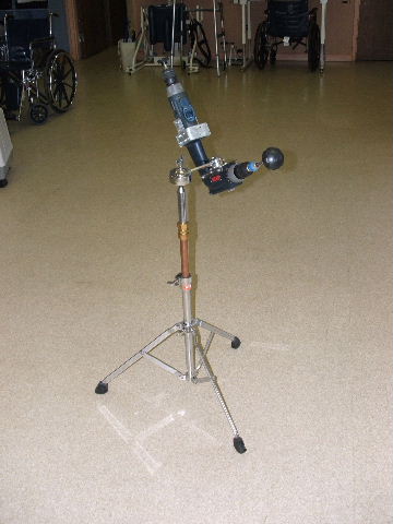
[ Home | List a patent | Manage your account | F.A.Q.|Terms of use | Contact us]
Copyright PatentAuction.com 2004-2017
Page created at 2026-01-11 13:37:28, Patent Auction Time.