Home List your patent My account Help Support us
DEVICE FOR AUTOMATIC ADJUST. OF POSITION OF TOOLS IN ROTARY HARROW
[Category : - MECHANICAL ENGINEERING- Agriculture- Lawn and Garden]
[Viewed 1027 times]
CLAIMS
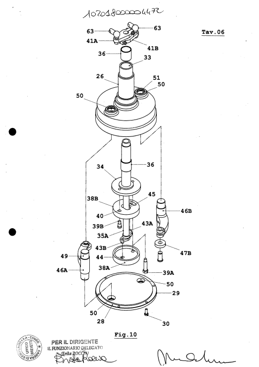
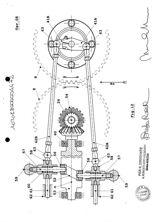
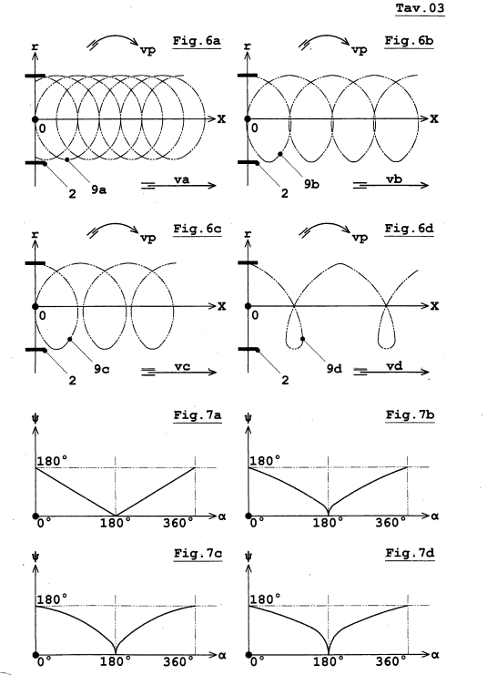
1. Improved rotary harrow device (1) comprising at least a frame (63) connected to at least one bevel gear unit (64) to which is inferiorly connected a transmission unit (11) to which are connected rotating supports (5) comprising a plurality of pairs of tools (2) arranged vertically, said frame being connected by means of a three-point attachment with a tractor machine (4), said bevel gear unit (64) being connected by means of a cardan shaft (65) to a power take-off of the tractor, said rotating harrow device being characterized by the fact that said harrow further includes at least one device (200) for the automatic adjustment of the position of a pair of tools (2) with respect to an axis (7) of rotation, said device (200) comprising at least one mechanical control unit (201) and one motion transmission unit (202) between said control unit (201) and said tools (2), said unit (201) comprising at least one cam (53) to which are connected mechanical means (210) to which are connected control levers (42A,42B) which are in turn connected to levers (41 A, 41 B) of unit (201), said levers (41 A, 41 B) being connected to said motion transmission unit (202), said unit (202) includes levers (46A.46B) which are connected to said tools (2), said unit (202) between said levers (41 A, 41 B) and said levers (46A.46B) comprising a plurality of shafts (26,35A,35B) and circular eccentrics (38A.38B), said shafts (35A.35B) being connected to the levers (41 A, 41 B) and being connected to said eccentrics which are in contact with said levers (46A.46B), the grooved cam (53) of the unit (201) by rotating causes an oscillatory movement of the mechanical means (210), said means by oscillating putting in turn in oscillation said control levers (42A.42B) said control levers transmitting the oscillatory motion to the levers (41A.41 B), said levers transforming the oscillatory motion in rotary motion to the shafts (35A.35B), said shafts having axis of rotation (m) eccentric with respect to the circular eccentrics (38A.38B), said eccentrics push on the levers (46A.46B) determining a rotation of the tools (2) around an axis (7), the tools being therefore mobile and disposing themselves in their trajectory of displacement tangent to the curve of cycloidal displacement deriving from the rotary motion of the harrow and traslatory motion given by the advancement of the tractor (4).
2. Rotary harrow device (1) according to claim 1 , in which a plurality of cams (53) are provided that can be positioned on the same axis of revolution (n), each having its own groove (52) matching different conditions of predetermined speed of rotation (vp) and translation (va), and that can be replaced as needed, or a single circular cam (53) with several grooves (52) can be provided.
3. Rotary harrow device (1) according to the previous claims, in which the profile of the groove (52) directly determines the degree of rotation of the tools (2) on their own axes (7), and therefore the tangency of the tools to the completed trajectory derived from the rototranslatory motion impressed to the harrow.
4. Rotary harrow device (1) according to the previous claims, in which said mechanical means (210) include at least one spring (60) operated selector (59) to set the drive circular cam (53) to be used in operation according to the two speeds that are decided to be used.
5. Rotary harrow device (1) according to the previous claims, in which the choice of the profile (52), and therefore of the cam (53) to be used for a given operating condition can be made manually or automatically.
6. Rotary harrow device (1) according to the previous claims, in which the power transmission unit (202) in which said plurality of shafts (35A,35B), eccentrics (38A,38) and said levers (46A.46B) are enclosed during operation in a bell- shaped profile of said rotating shaft (26), which has in the lower part a housing
(27).
7. Rotary harrow device (1) according to the previous claims, in which said eccentrics (38A.38B) of the transmission group (202) are held integral to the rotating shaft (26) by pins (39A and 39B), allowing the rotation of each eccentric with respect to a hole (40) of the eccentric (38B), the oscillating movement of each eccentric is obtained by the movement of the levers (41 A and 41 B), attached to the control shafts (35A and 35B) and in turn operated by said control levers (42A and 42B), pins (43A and 43B) sliding inside appropriate slots (44A and 44B) obtained in each of the two eccentrics.
8. Rotary harrow device (1) according to the previous claims, in which the two circular eccentrics (38A and 38B) have the same external shape, but the eccentric (38B) further includes a slot (45) to allow passage of the drive shaft (35A).
9. Rotary harrow device (1) according to the above claims, in which said device (200) for the automatic adjustment of the position of a pair of tools is applied to each pair of tools (2) of rotating supports (5).
 Patent publications:
 WO 2019198062
Asking price:
Make an offer
Make an offer
 Great invention
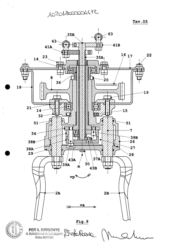
[ Home | List a patent | Manage your account | F.A.Q.|Terms of use | Contact us]
Copyright PatentAuction.com 2004-2017
Page created at 2025-11-27 12:15:25, Patent Auction Time.