Home List your patent My account Help Support us
Air jet power unit
[Category : - Motors]
[Viewed 1102 times]
Hello. This introduction is translated online by a translator. Text after entry by a professional translator. My name is Shokhin Nikolay +79296563340. I present to you a power plant that increases the efficiency and fuel efficiency of turbojet and turbo propeller, aircraft engines. And an example of how to achieve the efficiency of coaxial, turbo propeller and even turbojet engines, as well as possibly overcome the locking effect by having only one propeller, and not two, and also improve the fuel efficiency and speed of turbojet and turbofan engines simply by installing my power plant on the engines and not changing anything in the engines themselves. The power plant can be installed in the same housing as the engine or docked to the nozzle of the engine gandola. The power plant shall be docked to turbojet or turbofan engines. It is not attached to the motor shaft but can be attached. And driven by engine exhaust jet.
Power plant consists of tubes installed in round housing, passing through this housing and passing into blades, which are located outside the housing. The blades are pushing. Tubes are able to rotate inside this body, swirl around the central axis and the degree of twisting grows as it moves towards the blades. Approaching the angle of 90 degrees, the tubes are connected to the blades. Connection of tubes with blades allows setting of blade pitch control mechanism. Exhaust gases from the turbojet engine under pressure enter the tubes and begin to unscrew them and the associated propeller. Passing through tubes they are spun and enter internal channels of blades connected to them. Then they exit through slotted nozzles of blades mixing with air flow created by outer part of blade and it is significantly strengthened. Just behind the blades due to several factors.
A conventional screw not only conveys the mass of air backwards, but also substantially twists it around its axis. Thus, a significant portion of the power is used to unwind the air flow instead of being completely converted into the energy of its translational motion. In the blades of my power plant, the problem of swirling the air flow exiting the slot nozzles with air is solved. Which compensates for the twisting of the airflow by aligning it. Thus making the airflow more powerful. And also effectively mixing hot exhaust with cold. And then with the outside air. Thus reducing the thermal and inversion trace. This can be useful for combat aircraft. Also, my power plant can be used in the version of a pushing impeller or as a two-circuit pushing option. When the blades form the outer contour fan. Also, my power plant can be installed in the classic turbojet engine company in front. The idea is also applicable to turbine blades.
+79296563340 Nikolay.
UTILITY MODEL FORMULA
The aircraft propulsion, containing a turbojet engine pushing a jet-driven aircraft propeller, characterized in that the aircraft propeller is rotatably installed in the same housing with the turbojet engine immediately behind it. The rotor hub contains chambers-tubes communicating with the turbojet engine exhaust system, twisting in a spiral around a common longitudinal axis, while the twisting deflection of the chambers-tubes increases to an angle of 90 degrees at the point of joining with the blades. Inside each blade there is an air channel connected to the chambers-tubes, each blade contains a longitudinal (slot) nozzle located along the trailing edge along the entire blade length, the slot nozzle has bridges. The propeller hub contains an end conical fairing. The rotor hub is attached to the turbojet engine exhaust pipe and to the common housing by means of bearings. A graphite labyrinth seal is installed between the turbojet engine exhaust pipe and the rotor hub.
ABSTRACT
The invention relates to aviation, specifically, to the design of jet-driven propellers for aircraft. The aircraft propulsion contains a turbojet engine pushing a jet-driven aircraft propeller, while the aircraft propeller is installed in the same housing with the turbojet engine immediately behind it. The rotor hub contains chambers-tubes communicating with the turbojet engine exhaust system, twisting in a spiral around a common longitudinal axis, while the twisting deflection of the chambers-tubes increases to an angle of 90 degrees at the point of joining with the blades. Inside each blade there is an air channel connected to the chambers-tubes, each blade contains a longitudinal (slot) nozzle located along the trailing edge along the entire blade length, the slot nozzle has bridges. The propeller hub contains an end conical fairing. The reduction of the energy loss of the turbojet engine gas flow used to drive the propeller jet is provided. 2 views.
B64C 11/02
B64C 27/18
AIRCRAFT PROPULSION
The utility model relates to aviation, specifically, to the design of jet-driven propellers for aircraft.
Various designs of aircraft propulsions are known in the prior art.
So, a device for controlling the jet drive of the helicopter rotor, which consists of an aircraft propulsion, a compressor, a rotor hub, blades, pipelines, slot nozzles, the long side of which is located along the trailing edge, slot nozzles, the long side of which is located along the line of maximum relative profile thicknesses of the blade cross sections, strength ribs, is known from the description to the patent of the Russian Federation No. 2569233 C1 (publication date: 20.11.2015).
A propeller motor disclosed in the description of the patent of the Russian Federation No. 2102280 C1 (publication date: 20.01.1998) was selected as the closest analogue to the patentable solution. The known solution contains a jet-driven aircraft propeller, installed behind the engine in the same housing with it, contains a gas duct, blades with internal channels, and a nozzle on the trailing edge of the blade, while the gas from the rotary engine through the gas duct is directed into the blade channels to the outlet slot nozzles in the trailing edge of the blade, which ensures the rotation of the aircraft propeller.
The disadvantage of the known solution is that when the gas jet is turned at once by 90 degrees at the junction of the rotor hub and the blades, there is a large loss of gas jet energy leaving the engine.
The elimination of these disadvantages is the technical problem of the proposed technical solution.
The technical result is the elimination of the propulsive moment of the aircraft propeller, the reduction of gas jet energy losses used for the aircraft propeller jet drive, the expansion of the technical means arsenal.
The specified technical result is achieved by the fact that the aircraft propulsion contains a turbojet engine pushing a jet-driven aircraft propeller, while the aircraft propeller is installed in the same housing with the turbojet engine immediately behind it. The rotor hub contains chambers-tubes communicating with the exhaust pipe of the turbojet engine, twisting in a spiral around a common longitudinal axis, while the twisting deflection of the chambers-tubes increases to an angle of 90 degrees at the point of joining with the blades. Inside each blade there is an air channel connected to the chambers-tubes, each blade contains a longitudinal (slot) nozzle located along the trailing edge along the entire blade length, the slot nozzle has bridges. The propeller hub contains an end conical fairing. The rotor hub is attached to the exhaust pipe of the turbojet engine and the housing common with the turbojet engine with the possibility of rotation by means of thrust ball bearings. A graphite labyrinth seal is installed between the end of the exhaust pipe and the housing of the chambers-tubes, which seals the joint.
The declared technical solution is illustrated by reference to the views, which depict the following.
View 1 – a general view of the aircraft propulsion;
View 2 – an enlarged view of the blade.
The aircraft propulsion contains a turbojet engine (not shown) and an aircraft propeller (1). The aircraft propeller includes a hub (not shown) and blades (2). The rotor hub contains chambers (3) made in the form of tubes twisting in a spiral around a common longitudinal axis. Inside each blade there is an air channel (4) connected to the chambers-tubes (3). Each blade contains a longitudinal (slot) nozzle (5) located along the trailing edge along the entire blade length (2). The slot nozzle (5) has profiled bridges (6). The rotor hub contains an end conical fairing (7). The rotor hub is attached to the turbojet engine exhaust pipe and to the common housing (nacelle) by means of bearings. A graphite labyrinth seal is used to seal the joint between the exhaust pipe and the housing of the chambers-tubes.
The aircraft propulsion is installed immediately behind the engine, in one housing (nacelle), but it is not connected to the engine by a shaft. The jet flame coming out of the engine branch pipe enters the chambers-tubes, evenly dividing the inlet between them. As a result, kinetic energy is transferred through the tube chambers and the blade channels to the profiled slot nozzles located along the trailing edges of the blades due to the twisting of the chambers-tubes around a common axis, the blade angle of attack, and the gas pressure.
 Patent publications:
No publication
Asking price:
Make an offer
Make an offer
 Great invention
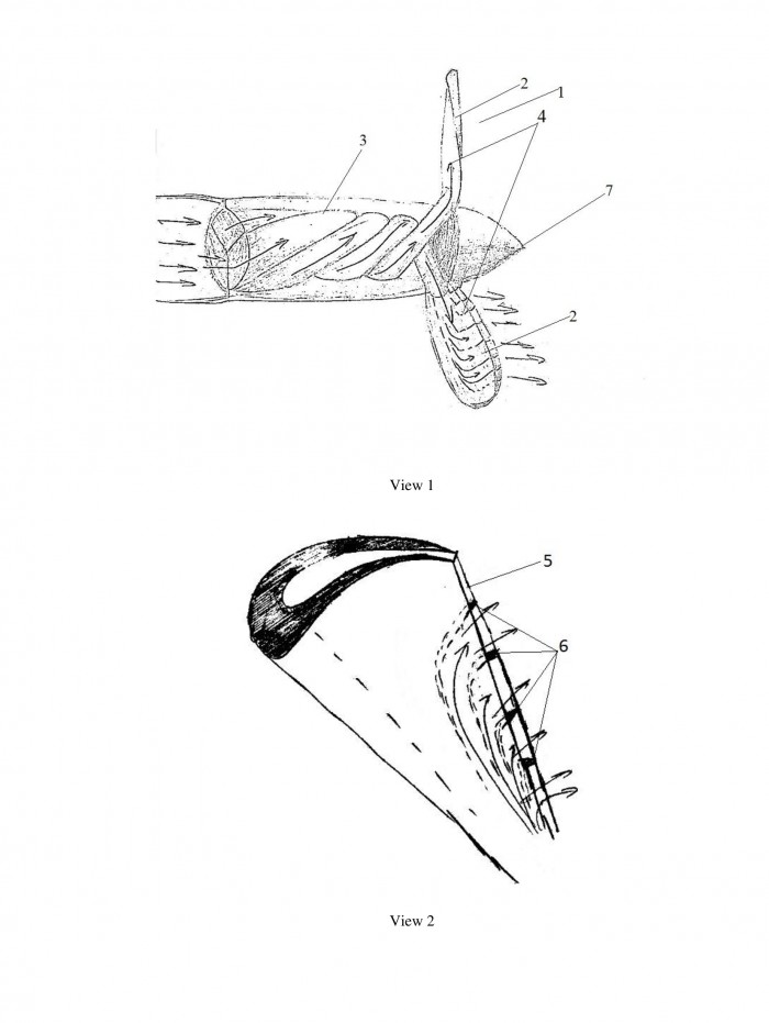

[ Home | List a patent | Manage your account | F.A.Q.|Terms of use | Contact us]
Copyright PatentAuction.com 2004-2017
Page created at 2025-12-21 0:27:50, Patent Auction Time.