Home List your patent My account Help Support us
Socket extensipn
[Category : - OTHER- CONSTRUCTION HOME IMPROVEMENT- ELECTRICITY & LIGHTING]
[Viewed 2295 times]
FIELD OF THE INVENTION
The present invention relates generally to an outlet assembly, particularly a wall embedded variant that permits the mobile socket to be retrieved and extended from the wall and outlet unit.
BACKGROUND OF THE INVENTION
Presently, wall outlets are very rigid and stationary objects, and any means to extend the power grid of the house requires the use of an extraneous extension cable that is then plugged into the outlet and led to the point the user desires power. Presently there is no acknowledged manner of integrating an extension capability directly into a wall socket without first falling into the category of the first instance. The present invention would therefore seek to surmount this void by offering an assembly that implements a spool within a gangbox or other known electrical housing that further employs a spool spring unit to allow the module cable running along the spool and to the mobile unit to separate and extend from the wall outlet from an outlet cradle to a desired length. When the user desires to rescind the cable, the user may tug on the mobile socket and the spool spring unit will retract the cable until the mobile socket rests within the outlet cradle once more. Whereupon the user may press down on the mobile socket to lock the outlet thereof into place through the plurality of spring push locks. Whereupon a user may then disengage the mobile socket from locking by pressing down again before pulling the mobile socket from the cover plate and outlet cradle. Thus, the invention has provided an assembly and means thereof that allows the mobile socket to be modularly extended and retracted into the wall, effectively circumventing the need for a conventional extension cable while simultaneously offering the user the ability to illuminate the area in proximity to the wall outlet through the illumination means and aperture on the cover plate.
BRIEF DESCRIPTION OF THE DRAWINGS
FIG. 1 is a perspective view of the apparatus and assembly where the outlet unit is situated between the cover plate and the gangbox where the extraneous electrical cable has been omitted but the extraneous electrical cable aperture is observed on the top surface of the gangbox.
FIG. 2 is a front sectional view of the apparatus thereof where the illumination aperture exposes the illumination source within the light unit and it is assumed that the illumination aperture screen is clear or transparent.
FIG. 3 is a right sectional view of the apparatus thereof where the plurality of gangbox-stud apertures is engaged with the plurality of stud apertures to secure the gangbox unit to the stud. Further observed is the plurality of outlet-gangbox fasteners that connect to the gangbox unit.
FIG. 4 is a left sectional view of the apparatus thereof.
FIG. 5 is a rear sectional view of the apparatus thereof where the plurality of spool locking nuts are observed on the spool axle.
FIG. 6 is a top sectional view of the apparatus thereof where the socket cable is observed merging into a single cable as the cable thereof progresses into the gangbox cavity.
FIG. 7 is a bottom sectional view of the apparatus thereof where the mobile socket is observed disparate of the outlet unit.
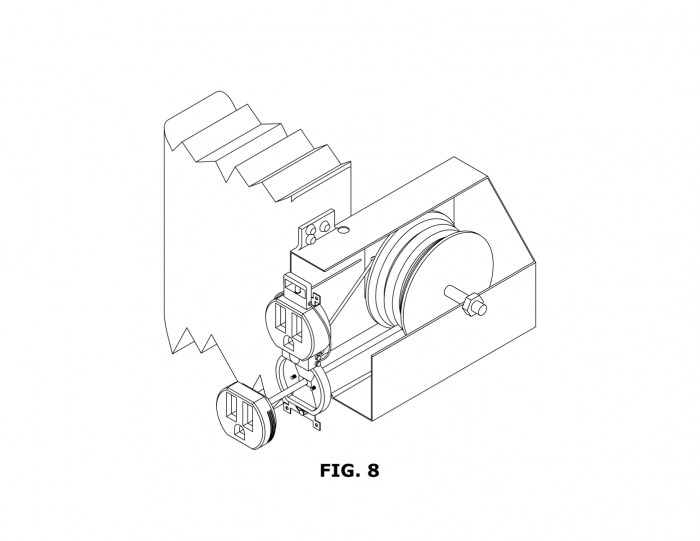
FIG. 8 is a perspective view of the apparatus where the cover plate has been omitted and the mobile socket has been extended from the outlet cradle and the plurality of ridges are exposed. Further, the gangbox has been sectioned open to expose the spool, spool axle, spool spring unit, and the socket cable inlet are observed. Further still the socket cable is observed connected to the top plurality of power nodes. Still further, the plurality of spring push locks is observed in the outlet cradle with the module cable aperture located at the center thereof.
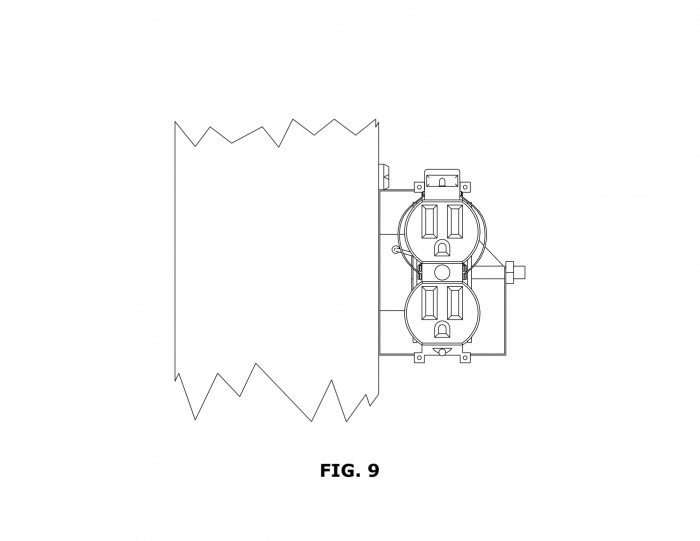
FIG. 9 is a front sectional view of the apparatus thereof where the plurality of wires is observed and connected between the bottom plurality of power nodes and the plurality of illumination nodes where additionally the plurality of outlet apertures and illumination means are further observed.
FIG. 10 is a diagram drawing of the present invention’s guide for the retractable cord.
DETAIL DESCRIPTIONS OF THE INVENTION
All illustrations of the drawings are for the purpose of describing selected versions of the present invention and are not intended to limit the scope of the present invention.
In reference to FIGS. 1-9, the present invention is a wall socket assembly that permits the extension and retraction of a mobile socket primarily through an outlet unit, a gangbox unit, a cover plate, an extraneous drywall, an extraneous stud, and an extraneous electrical cable. The outlet unit comprises a stationary socket, a mobile socket, a plurality of power nodes, a socket cable, a plurality of outlet fastening apertures, an outlet cover aperture, and a light unit that further comprises a plurality of light nodes, an illumination source, and a plurality of wires. The mobile socket further comprises a module cable inlet, a plurality of spring push lock apertures, a plurality of ridges, and an outlet cradle that further still comprises a module cable aperture, and a plurality of spring push locks. The plurality of outlet fastening apertures further comprises a plurality of outlet-gangbox fasteners. The gangbox unit comprises a gangbox body that further comprises a plurality of gangbox-spool apertures, a plurality of gangbox-stud apertures, a plurality of gangbox-outlet apertures, an extraneous electrical cable aperture, and a gangbox cavity. The plurality of gangbox-stud apertures further still comprises a plurality of stud fasteners. The gangbox itself further still comprises a spool that still further comprises a spool axle, a spool spring unit, and a module cable. The spool axle still further comprises a plurality of spool locking nuts, and the spool spring unit still further comprises a socket cable inlet. Lastly, the cover plate comprises a plurality of socket apertures, an outlet-cover aperture, and an illumination aperture. The outlet-cover aperture further still comprises a cover-outlet fastener, and the illumination aperture further still comprises an illumination aperture screen.
In particular reference to FIGS. 1-4 and 6-9, the outlet unit is located between the cover plate coincident and adjacent to the extraneous drywall, and to the front of the gangbox unit. The outlet unit would allow for the transmission of electricity and permit the extension of the mobile socket. The outlet unit further may be fastened to both the extraneous drywall and the gangbox rigidly. Further still, the outlet unit is to be powered through a conventional electrical cable such as but not limited to Romex and other cables known to the industry in conventional wiring arrangements to the plurality of power nodes.
Located at the top of the outlet unit and above the outlet cover aperture and the mobile socket is the stationary socket that remains fixed behind and within the cover plate. The stationary socket otherwise would function as a conventional outlet but may be exchanged for a mobile socket if a second spool is provided. Located at the bottom of the outlet unit is the mobile socket that may be pressed to disengage from the plurality of spring push locks and pulled from the lower outlet aperture preferably to pull and extend the mobile socket to the desired location of the user. The mobile socket would be extendable by means of the module cable fed by the spool within the gangbox unit and would be wired independently from the plurality of power nodes.
At the rear of the mobile socket at the center thereof is the mobile cable inlet that secured the module cable in place securely when the mobile socket is disengaged from the outlet unit and extended from the extraneous drywall. Located on the rear surface of the mobile socket and aligned with the plurality of spring push locks is the plurality of spring push lock apertures that allows the mobile socket to be pressed into place and disengaged from the outlet cradle as needed. Further, the plurality of spring push lock apertures would preferably be composed of a count of two. Along the sides of the mobile socket is the plurality of ridges that are preferably located near the rear most edge of the side surfaces and preferably unseen when locked into the cradle but exposed when disengaging the plurality of spring push locks. The plurality of ridges would provide a surface for the user to grip to ease extraction of the mobile socket from the cover plate. Intended to house the mobile socket’s rear surface and located on the bottom of the outlet unit facing outward from the extraneous drywall is the outlet cradle. The outlet cradle forms a preferably funnel equivalent function that directs the mobile socket while firmly securing into the wall when locked into place.
Located at the center of the outlet cradle surface nearest the rear is the module cable aperture that allows the module cable to transmit through and allow the mobile socket to extend from the outlet unit. Protruding from the surface with a pressure driven locking mechanism at points coincident with the plurality of spring push lock apertures to lock the mobile socket into the outlet unit and disengage when pressed down by the user is the plurality of spring push locks that interact and lock the mobile socket in place.
Located preferably on the sides of the outlet unit below the stationary socket and above the mobile socket is the plurality of power nodes composed of a preferable count of four with two on each side in a conventional arrangement similar to known electrical outlets. Preferably however, the top two plurality of power nodes would be wired to the plurality of light nodes in a parallel arrangement and the bottom two plurality of power nodes to be wired to the socket cable inlet in a fixed or rigidly tethered arrangement. Affixed to the top plurality of power nodes and connecting to the socket cable inlet is the socket cable that transfers the power intended for the mobile unit to the gangbox unit, spool, and module cable. The socket cable would further preferably originate from the top plurality of power nodes and merge together into a single cable or sheath.
Located on the top and bottom surfaces of the outlet unit is the plurality of outlet fastening apertures that are preferably composed into two sets. Further preferably each set of the plurality of outlet fastening apertures would possess two curvilinear apertures at the edges to permit fastening to the extraneous drywall and a larger center aperture that would permit the passage of an outlet gangbox fastener. Engaging with the plurality of outlet fastening apertures and specifically the center most apertures is the plurality of outlet gangbox fasteners that are composed of at least two fasteners therein that may be passed through an aperture produced in the extraneous drywall, firmly affixing the outlet unit to the gangbox unit.
Located at the center front surface of the outlet unit below the stationary socket and above the mobile socket is the outlet cover aperture that permits the cover plate to be fastened to the outlet unit. Protruding from the top surface of the outlet unit is the light unit that allows the outlet itself to produce illumination in proximity to the stationary and mobile sockets on the exterior of the cover plate and into the room. The light unit itself would comprise a further recess or housing that seats the illumination source where the light unit housing may possess a reflective or illumination amplifying means. Located on the lateral sides of the light unit is the plurality of light nodes that are connected in parallel to the bottom two plurality of power nodes through the plurality of wire where the light nodes may be screwed, fastened or spring loaded to retain the plurality of wires. Located in the light unit housing is the illumination source that is supplied power through the plurality of light nodes. The illumination source would preferably be composed of an LED or a plurality thereof that may additionally utilize a resistive element or fuse to prevent overloading or overheating the illumination source. Connecting between the plurality of light nodes and the two bottom nodes of the plurality of power nodes is the plurality of wire that connects between the two node sets, producing a parallel connection that powers the illumination source.
In particular reference to FIGS. 1, 3-6, and 8, located at the rear of the apparatus is the gangbox unit that houses the spool and enables the mobile socket to be extended and retracted. The gangbox is further set adjacent to the extraneous stud and fastened thereto and simultaneous located behind the extraneous drywall. The gangbox unit further houses the spool, directs the extraneous electrical cable, and affixes to the outlet unit. The gangbox body is a preferably rectilinear body with a cavity therein and at least one exposed side formed preferably at the lateral front surface of the gangbox. Located on the major faces of the gangbox along the vertical center is the plurality of gangbox-spool apertures where a count of two is preferred and aligned to one another on opposing walls so as to suspend the spool axle in a horizontal orientation.
Preferably located on a protrusion emanating from the top surface along the longitudinal edge and near the front surface of the gangbox as a flat planar protrusion is the plurality of gangbox-stud apertures that are composed of a preferable count of three in an arbitrary arrangement to arrest the motion of the gangbox entirely when engaged by the plurality of stud fasteners. Engaging with the plurality of gangbox-stud apertures and composed of an equivalent count is the plurality of stud fasteners that affix the gangbox firmly to the stud.
Located within the gangbox cavity along the top and bottom surfaces is the plurality of gangbox-outlet apertures that allow the gangbox unit to be affixed to the outlet unit by engagement with the plurality of outlet-gangbox fasteners. Located on the top surface of the gangbox and near or adjacent to the plurality of gangbox-stud apertures protrusion is the extraneous electrical cable aperture that allows passage and a means of securing the extraneous electrical cable through the gangbox before wiring into the plurality of power nodes of the outlet unit. Formed in the center of the gangbox body is the gangbox cavity that houses the spool and associated elements while additionally mitigating exposure of the socket cable, extraneous electrical cable and module cable. The gang box cavity generally produced a shelled wall of the gangbox body to optimize available space for the spool and module cable to accommodate.
Concentric with the spool axle and adjacent to the spool spring unit is the spool, allowing the module cable to wind and unwind as needed by the user where the spool spring unit permits the module cable to be retracted by tugging and releasing. Coincident and running through the plurality of gangbox-spool apertures, the spool, and the spool spring unit is the spool axle that permits the spool itself to be spun about the axial direction to wind and unwind the module cable. Further, the spool axle would preferably be secured by the plurality of spool locking nuts located on the exterior of the gang box. Concentric to the spool axle, located on the exterior of the gangbox and adjacent thereto is the plurality of spool locking nuts that arrest the rotational motion of the spool axle and translational motion between the plurality of gangbox-spool apertures. The plurality of spool locking nuts would further preferably be composed of a count of two.
Originating from the spool spring unit and in continuity with the socket cable is the module cable that winds around the spool and connects to the module cable inlet located on the mobile socket. The module cable would permit the mobile socket to be retrieved and extended from the outlet unit when the mobile socket is disengaged from the outlet cradle. Located adjacent to the spring, secured along the spool axle, and adjacent to the interior surface of the gangbox is the spool spring unit that accepts the socket cable, and transfers continuity to the module cable secured around the spool. The spool spring unit further provides a spring loaded ratcheted rotation mechanism that allows the module cable to be unwound and extended and when tugged rewound where the mobile socket is pulled back into the outlet unit. Located on the front facing surface of the spool spring unit is the socket cable inlet that allows the passage and acceptance of the socket cable from the top two power nodes of the plurality of nodes.
In particular reference to FIGS. 1 and 2, the cover plate is located at the front of the apparatus, exterior to the extraneous drywall and secured to the outlet unit while providing a plurality of apertures to secure and expose the stationary socket, mobile socket, and the illumination source. Located at points coincident with the stationary and mobile socket in a count of at least two is the plurality of socket apertures that expose the stationary and mobile sockets. Located at the center of the cover plate, below the stationary socket, and above the mobile socket is the outlet-cover aperture that allows the cover plate to be affixed to the outlet unit. Engaging with the cover-outlet aperture and the outlet-cover aperture is the cover-outlet fastener that affixes the cover plate securely to the outlet unit through fasteners including but not limited to: screws, bolts, snap fits, and so on. Located above the topmost outlet aperture of the plurality of apertures is the illumination aperture that preferably possesses a rectilinear geometry and provides a passage for light produced by the illumination source. Further located coincident with the illumination aperture is the illumination aperture screen that provides a protective cover for the illumination means housed behind the cover plate.
In reference to FIGS. 1-9, disparate of the apparatus but ancillary to the function thereof is the extraneous stud that the apparatus must preferably be installed in proximity to. The extraneous stud would provide a means of grounding the gangbox unit and subsequently the spool and module cable to the wall to provide a sturdy extension and retraction of the module cable. Further disparate of the apparatus but necessary to the function thereof is the extraneous electrical cable; omitted from the illustrated figures, such as Romex that provides power to the outlet unit from the power grid of the building by linking to the plurality of power nodes as though the outlet unit of the apparatus were a conventional outlet. Lastly, the extraneous drywall is generally provided in a house where an aperture must be carved therein to implant the gangbox unit, the outlet unit, and the cover plate.
In reference to FIG. 10, the present invention also consists of a guide for the retractable cord. The guide helps the cord rewind on the spool evenly.
Although the invention has been explained in relation to its preferred embodiment, it is to be understood that many other possible modifications and variations can be made without departing from the spirit and scope of the invention.
 Patent publications:
No publication
Asking price:
Make an offer
Make an offer
 Great invention
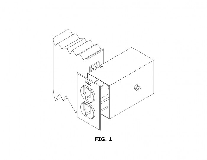
[ Home | List a patent | Manage your account | F.A.Q.|Terms of use | Contact us]
Copyright PatentAuction.com 2004-2017
Page created at 2025-12-27 14:18:10, Patent Auction Time.